The DB 605 was a development of the DB 601 and was very similar in basic
construction to that power unit. The main improvements increased the maximum permissible
r.p.m..
Altered valve timing increased the inlet period and improved the scavenging to give
greater volumetric efficiency at higher r.p.m.
A complete redesign of the cylinder block obtained the maximum possible bore with existing
cylinder centers. The new design also repositioned the spark plugs. The cranksahft big-end
bearings were also modified.
CONSTRUCTION: Cylinder barrels of steel are screwed and shrunk into the
cast Silium-Gamma-alloy cylinder blocks. These dry liners project beyond block providing
attachment by means of threaded rings which pull the liners against the finished face of
the crankcase.
Two inlet and two exhaust valves per cylinder operated by rocker arms directly from a
single camshaft carried upon the head. Stellited valve seats, exhaust valve sodium cooled,
ball joints interpose rockers and valve stems.
Forged light-alloy pistons have concave heads, each piston has a floating pin and three
compression and two oil-scraper rings with one below the pin.
Forked type connecting rods with serrated joints at big ends, roller bearing at big end
has three tracks of 24 rollers each. Forked rod is keyed to outside of roller race, plain
rod runs on lead-bronze bearing over race.
One piece forged steel crankshaft carried in seven plain lead-bronze bearings. Eight
balance weights attached to crank webs, splined forward end to receive splined sleeve of
reduction gear pinion.
Deep light alloy crankcase with webs at main bearings, tubular mounting at rear below
crankshaft for installation of cannon which can fire through propeller shaft, light top
cover.
Centrifugal supercharger on port side of engine driven through a fluid coupling by a shaft
at right angles to crankshaft. This shaft is driven through bevel gears from the
crankshaft, variation in propeller speed secured through variable filling of fluid
coupling by two-stage enginedriven pump receiving lubricating oil from the main pressure
filter.
First stage delivers oil direct to coupling and second stage delivery is passed in varying
proportions between crankcase and coupling by piston valve controlled by a capsule which
is sensitive to inlet pressure. Second stage cuts in at approximately 5,000 ft. and full
delivery occurs at approximately 11,500 ft.
Butterfly throttle which is capsule controlled regulates supercharger delivery, second
throttle which is pilot operated controls air supply to engine and manifold pressure,
first throttle subjected to pressure between two throttles, increased boost for take-off
controlled by clockwork mechanism, mixture delivered by supercharger to looped manifold by
large diameter pipe, dry-sump pressure-feed lubrication, gear type oil pumps, spray of oil
directed upon reduction gears, main oil pressure line feeds crankshaft bearings, secondary
line feeds supercharger fluid pump.
Scavenging pumps at rear end of camshafts, single spur type propeller reduction gears,
provision for mounting controllable-pitch full-feathering propeller, centrifugal pump
circulates coolant consisting of equal parts water and ethylene-glycol.
Supercharged DB 605 D aircraft engine
Type: Liquid-cooled, inverted V12
Displacement: N/A
Rated Horsepower: Normal 2,000hp
DB 605 Am
Type: Liguid-cooled, inverted V12
Displacement: N/A
Rated Horsepower: Normal 1,475hp at take-off 1,355hp at 13,450ft
Rated Horsepower: With MW 50 (Methanol/Water) injection 1,800hp at take-off 1,700hp at
13,450ft
Aces Home Page | U. S. Fighter Home Page | Feedback
Allison V-1710-85 Engine and drivetrain for P-39Q
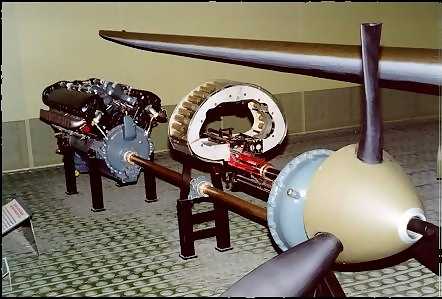 In the aircraft
designer's search for better streamlining and higher speeds, some aircraft were designed
with the large and heavy engine mounted amidships and the propeller driven by an extension
shaft which passed between the pilot's feet. This permitted the nose contours of the
fuselage to be shaped to reduce drag. This arrangement also permitted a larger cannon to
be mounted within the contours of the fuselage and fired through the propeller shaft. The
layout of the P-39 Airacobra is shown here. It includes an Allison
V-1710 engine, the drive shaft, the offset reduction gearbox, and the Aeroproducts
propeller. Aft mounted engines were later employed on Bell's follow-on aircraft, the P-63
"King Cobra", and later the larger
In the aircraft
designer's search for better streamlining and higher speeds, some aircraft were designed
with the large and heavy engine mounted amidships and the propeller driven by an extension
shaft which passed between the pilot's feet. This permitted the nose contours of the
fuselage to be shaped to reduce drag. This arrangement also permitted a larger cannon to
be mounted within the contours of the fuselage and fired through the propeller shaft. The
layout of the P-39 Airacobra is shown here. It includes an Allison
V-1710 engine, the drive shaft, the offset reduction gearbox, and the Aeroproducts
propeller. Aft mounted engines were later employed on Bell's follow-on aircraft, the P-63
"King Cobra", and later the larger 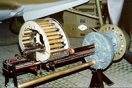 Fisher P-75.
The V-1710 liquid-cooled engine shown here was first used by the Army Air Corps in 1932 and, with later improvements, powered most Curtiss P-40 "Warhawks," the twin engined Lockheed P-38 "Lightning," the early versions of the North American P-51 "Mustang" and, as late as the 1950's, some F-82 "Twin Mustangs."
V-1710-85 driveshaft and 20mm cannon
SPECIFICATIONS
Model: V-1710-85
Type: 12 cylinder, liquid-cooled, 'V' type with single-stage, mechanically-driven
supercharger
Displacement: 1,710 cu.in.
Weight: 1,445 lbs. (including drive shaft, gear box, and propeller shaft)
Maximum RPM: 3,000
Maximum Horsepower: 1,325
Cost: $11,810 (engine only)
Courtesy U.S. Air Force Museum
Aces Home Page | U. S. Fighter Home Page | Feedback
General
Electric J47 Turbojet Engine
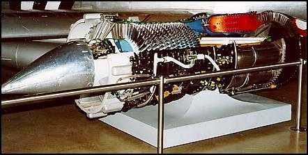 The J47 was developed by the General Electric Company from
the earlier J35 engine and was first flight-tested in May 1948 as a replacement for the
J35 used in the North American XF-86 "Sabre". In September 1948, a J47 powered
an F-86A to a new world's speed record of 670.981 miles per hour. More than 30,000 engines
of the basic J47 type were built before production ended in 1956. The engine was produced
in at least 17 different series and was used to power such Air Force aircraft as the F-86, XF-91, B-36, B-45, B-47, and XB-51.
The J47 was developed by the General Electric Company from
the earlier J35 engine and was first flight-tested in May 1948 as a replacement for the
J35 used in the North American XF-86 "Sabre". In September 1948, a J47 powered
an F-86A to a new world's speed record of 670.981 miles per hour. More than 30,000 engines
of the basic J47 type were built before production ended in 1956. The engine was produced
in at least 17 different series and was used to power such Air Force aircraft as the F-86, XF-91, B-36, B-45, B-47, and XB-51.
A J47-GE-7 engine became the first axial-flow (straight-through airflow)
engine in the United States to be approved for commercial use. The J47 was retired when
the last Boeing KC-97J was dropped from Air National Guard service in 1978. It thus
spanned 30 years of operational service.
SPECIFICATIONS
Model: J47-GE-25
Compressor: 12-stage axial
Turbine: single-stage axial
Weight: 2,707 lbs.
Thrust: 5,670 lbs.
Maximum RPM: 7,950
Maximum Operating Altitude: 50,000 ft.
Cost: $50,000
Courtesy U.S. Air Force Museum
Aces Home Page | U. S. Fighter Home Page | Feedback
General
Electric J-73 Turbojet Engine
The J-73 engine was developed by the General Electric Company from the J47 engine in the early 1950s. The more
powerful J-73 was used in F-86H aircraft instead of the J47 as in
earlier series F-86s. In September 1954, during the National Aircraft Show at Dayton,
Ohio, a J73 engine powered an F-86H to a world's speed record of 649.302 mph for a
500-kilometer closed course in the General Electric Trophy Event. At the same show, the
J73-powered F-86H also established a Thompson Trophy Event record of 692.818 mph over a
100-kilometer closed course.
SPECIFICATIONS
Model: J-73-GE-3E
Compressor: 12-stage axial
Turbine: two-stage axial
Thrust: 8,920 lbs. max.
Weight: 3,650 lbs.
Max. RPM: 7,950
Max. Operating Altitude: 65,000 ft.
Cost: $145,000
Courtesy U.S. Air Force Museum
Aces Home Page | U. S. Fighter Home Page | Feedback